

Assembly Methods for an External Acoustic Transmitter Attachment Device for Fish Telemetry Studies
Links
- Document: Report (1.52 MB pdf) , HTML , XML
- Download citation as: RIS | Dublin Core
Acknowledgments
Funding was provided by the U.S. Geological Survey Ecosystems Mission Area and the Great Lakes Restoration Initiative (https://www.usgs.gov/special-topics/great-lakes-restoration-initiative). Any use of trade, firm, or product names is for descriptive purposes only and does not imply endorsement by the U.S. Government.
Abstract
The purpose of this report is to describe the assembly methods for an external acoustic transmitter attachment device that can be used during fish telemetry studies. External attachment is a simple procedure that can limit handling and reduce recovery times on fish. This report provides step-by-step directions to assemble devices; this assembly method can be used for telemetry studies where external transmitter attachment is needed. General guidelines to attach transmitters to fish also are included.
Introduction
The purpose of this report is to describe the assembly methods for an external acoustic transmitter attachment device (EATAD) that can be used during fish telemetry studies. Telemetry studies often rely on surgically implanted or gastric inserted transmitters to retain acoustic transmitters within the fish (Wagner and others, 2011); however, external transmitter attachment also is beneficial in certain scenarios to limit handling and reduce recovery times (Runde and others, 2022). In pond or mesocosm studies, for example, acoustic transmitters may be externally attached to facilitate replicated trials and allow the fish to be monitored within hours to days after they are released (for example, Romine and others, 2015; Donaldson and others, 2016). This report provides step-by-step directions to assemble an EATAD that can be used for telemetry studies where external transmitter attachment is needed. General guidelines to attach transmitters to fish also are included.
Methods
The following instructions describe the assembly of EATADs for Hydroacoustic Technology Inc. model 795LD acoustic transmitters (Hydroacoustic Technology Inc., Seattle, Washington). Instructions are intended to be a procedural reference and may need to be modified if transmitters from a different manufacturer or model are used. Note that visual representations of each step are provided in photographs.
Disclaimer
Assembly of an EATAD using the following method may void the manufacturer’s warranty. Consult the manufacturer for guidance on tag use and warranty information. Materials or tools used for assembly of this attachment method may be substituted with equivalent materials or tools from other manufacturers, although methods may need to be modified accordingly.
External Transmitter Assembly
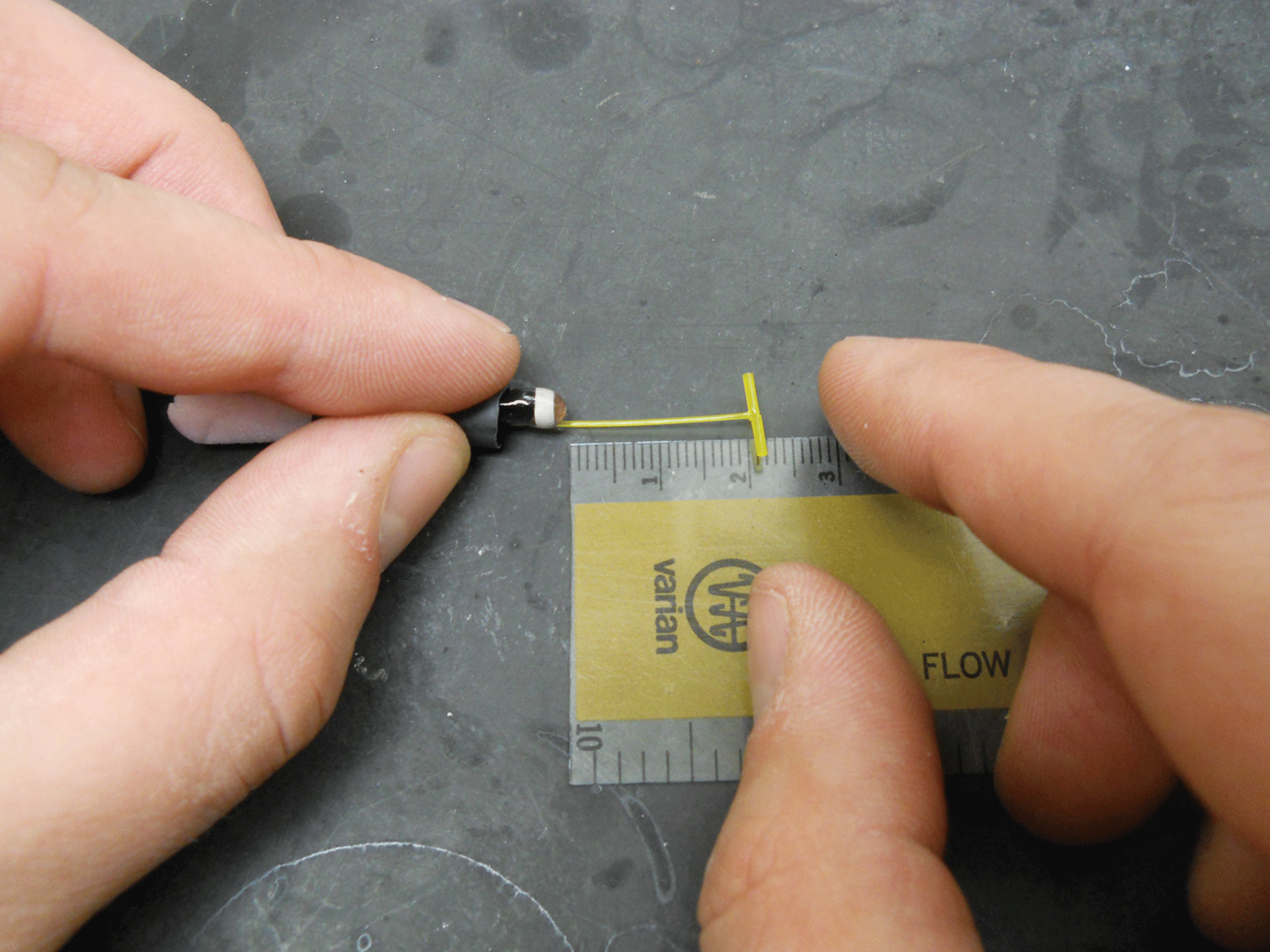
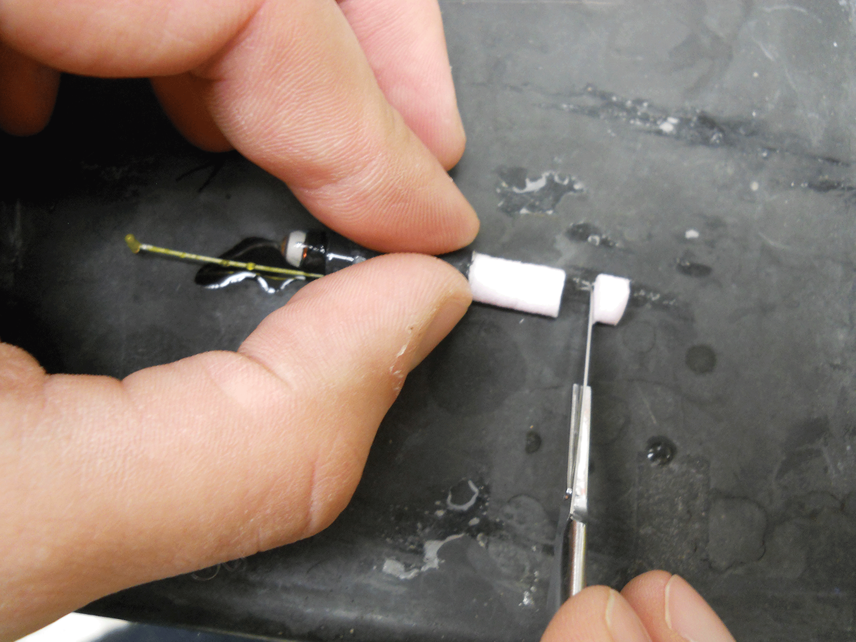
EATADs are constructed using construction-grade rigid foam insulation (for example, Foamular 250, Owens Corning, Toledo, Ohio) for buoyancy (fig. 1). Cut the foam into cylindrical plugs (about a 6-millimeter [mm] diameter and a 51-mm length) using a plug press and no. 3 plug bit (for example, Sargent-Welch Plug Press, Rochester, New York). Then, trim a T-bar-style anchor tag (for example, Floy Tag, Inc., Seattle, Wash.) monofilament whisker to a 50-mm length and insert perpendicular through the foam plug about 3 mm up from the bottom of the foam cylinder (fig. 2). Insert the foam plug and attached tag into adhesive-lined heat-shrink tubing (a 6.4-mm diameter and a 30-mm length; for example, BuyHeastShrink.com, Deerfield, Florida) while folding both ends of the tag towards each other to later accommodate the transmitter between the two ends (fig. 3). The pink foam will act as an anchor point for the tag and will reduce chances of it pulling out. The end of the pink foam should protrude from one end of the tubing and the T-bar end of the tag protruding from the other (fig. 3). Next, insert the battery end of the transmitter into the heat-shrink tubing with the folded tag covering each side (fig. 4). The end of the transmitter must be exposed to avoid obstructing the acoustic signal. Finally, pull the T-bar end of the tag to a 20-mm length (fig. 5) to provide a gap between the skin of the fish and the acoustic transmitter after the T-bar is attached to the fish, which will prevent rubbing or abrading the epidermal surface.
Materials used to construct an external acoustic transmitter attachment device. The acoustic transmitter (A) and foam plug (C) containing the T-bar tag (D) are inserted into the heat-shrink tubing (B) and bound together with heat into a completed tag assembly (far right). Photograph by Justin Smerud, U.S. Geological Survey.
Tag being inserted perpendicular through the end of the pink foam. Photograph by Kim Fredricks, U.S. Geological Survey.
Foam being pulled through the shrink tubing as the ends of the tag are folded down. Photograph by Samantha Wolfe, U.S. Geological Survey.
Transmitter and foam being inserted into the heat-shrink tubing. The battery end of the transmitter is inserted into the tubing. The transmitting end must be exposed to avoid obstructing the acoustic signal. Photograph by Kim Fredricks, U.S. Geological Survey.
The T-bar end of the tag is pulled away from the transmitting end of the transmitter to a 20-millimeter length. Photograph by Kim Fredricks, U.S. Geological Survey.
Gently hold the assembly with pliers and slowly apply heat to bind the materials together. Heat can be applied using a variable temperature heat gun (for example, Intertek, VT–1100, BuyHeatShrink.com, Deerfield Beach, Fla.) set to about 90 degrees Celsius (fig. 6). Slowly move the heat gun back and forth along the length of the assembly to avoid concentrating too much heat. Care must be taken to limit the amount of heat applied because it can damage the transmitter, tag, foam, and heat-shrink tubing. Continue applying heat until the heat-shrink tubing is fully compressed. Allow the EATAD to cool at room temperature until the heat-shrink tubing is hardened. Once cooled, place the EATAD into a beaker of room temperature water to check for neutral buoyancy. Incrementally cut the foam using a sharp blade until neutral buoyancy is achieved (fig. 7). The neutrally buoyant EATAD should stand upright with the T-bar resting on the bottom of the beaker (fig. 8). Typically, the foam will be cut flush with the end of the heat-shrink tubing (although it may protrude slightly), or the heat-shrink tubing may need to be slightly shaved. The amount removed will depend on variations in assembly and weight of materials. Any exposed material, such as pink foam insulation, can be colored using a waterproof black marker (for example, a Sharpie). Finally, unique identifiers such as the tag number can be written onto the black tubing to aid with tag inventory and identification using a waterproof or chalk marker (see markings on assembled transmitter in fig. 1).
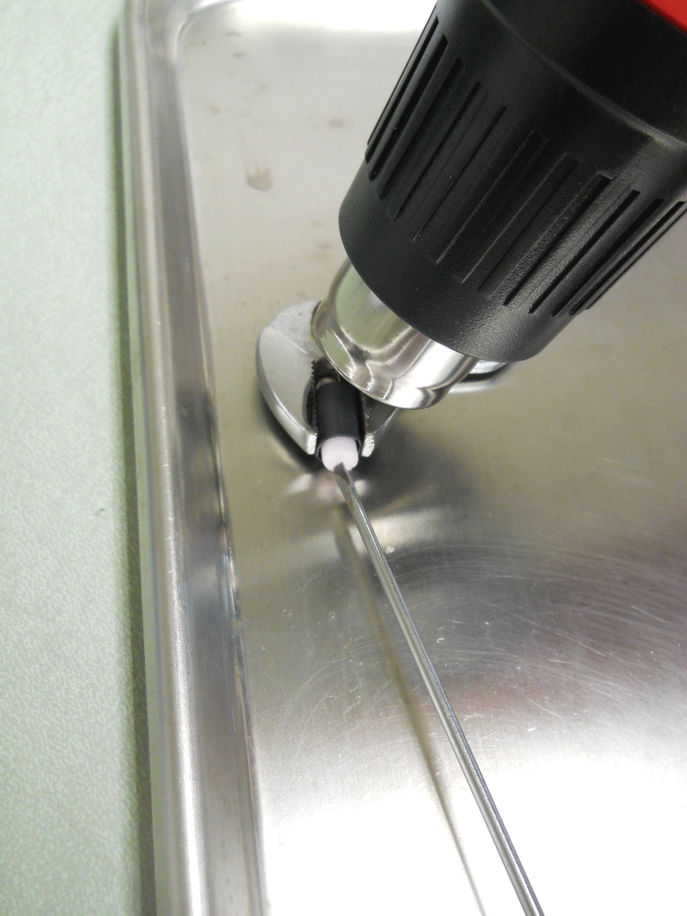
Pliers are used to loosely hold the external acoustic transmitter attachment device in place while heat is applied. Photograph by Kim Fredricks, U.S. Geological Survey.
The pink foam is incrementally cut away with a sharp blade until neutral buoyancy is achieved. Photograph by Kim Fredricks, U.S. Geological Survey.
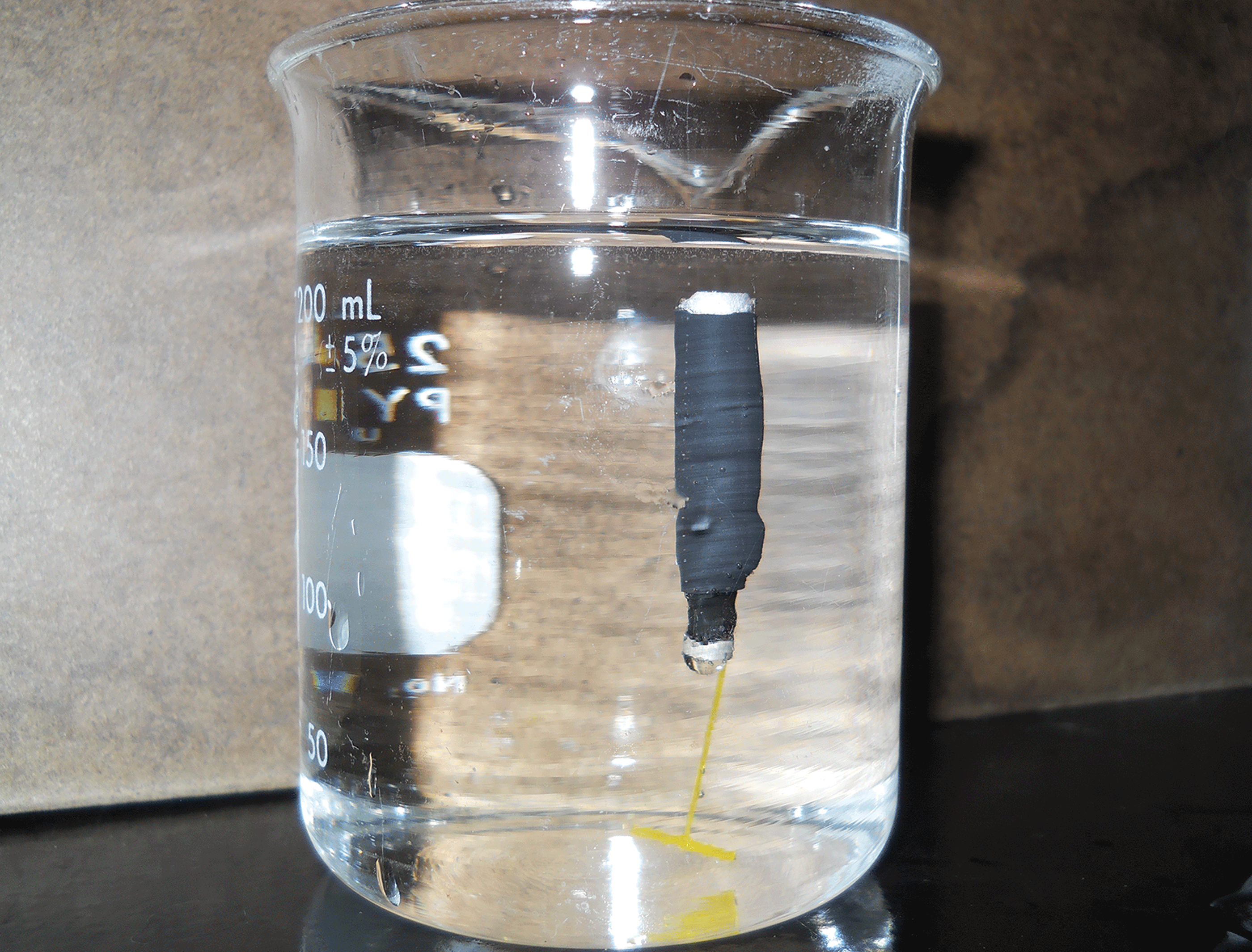
A neutrally buoyant external acoustic transmitter attachment device should stand upright when completely submerged underwater with the T-bar end of the tag resting on the bottom. Photograph by Kim Fredricks, U.S. Geological Survey.
Transmitter Attachment
The transmitter assembly can be externally attached to a fish using a scissors or pistol style T-bar anchor gun (for example, uline.com, Pleasant Prairie, Wisconsin). The attachment process is identical to the conventional T-bar anchor tag marking used in mark-recapture studies (Murphy and Willis, 1996). Disinfect the tag using a 3-percent solution of stock 2 percent chlorhexidine diacetate (for example, Nolvasan, Fort Dodge, Iowa) for 15 minutes and rinse with deionized water. Fish may require sedation to facilitate handling (Ross and Ross, 2008) in accordance with Institutional Animal Care and Use Committee standards. Insert the T-bar anchor into the muscle tissue of fish by positioning the T-bar anchor gun slightly posterior of the dorsal fin, about 10 mm to the left of the midline, in the white muscle at about a 30-degree angle (fig. 9). Distance from midline will depend on fish size and species. Inject the tag and rotate about 45 degrees before removing the needle from the fish (Murphy and Willis, 1996). Tags inserted in this manner should trail smoothly behind the fish while it is swimming. Risk of detachment because of tags catching on debris, and encounters with conspecifics is minimized during normal swimming behavior when the tag is positioned to the dorsal and posterior aspects of the body wall; however, the transmitter is still susceptible to entanglement because of external attachment. Neutral buoyancy of EATAD may reduce epidermal scraping on fish compared to a sinking transmitter.
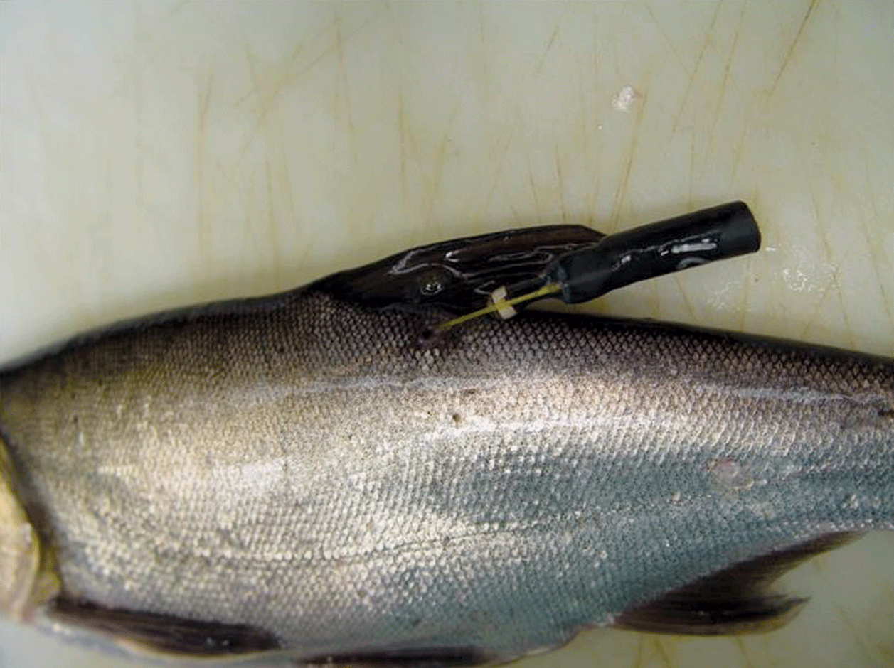
Positioning of a completed external acoustic transmitter attachment device attached to a fish. Photograph shows attachment to a juvenile Hypophthalmichthys molitrix (silver carp). Photograph by U.S. Geological Survey.
Tag Repair
Repairs can be made if the foam is damaged or broken. Cut a 20-mm piece of heat-shrink tubing and a 30-mm piece of 6-mm diameter foam insulation as previously described. Stretch the heat-shrink tubing and slide the tubing over the insulation end of the assembly. Insert the foam in the open end of the new heat-shrink tubing and compress the tubing using a heat gun. Cut away excess foam until the assembly is neutrally buoyant. Ideally, the foam should be flush with the insulation or slightly protruding in the completed assembly.
References Cited
Donaldson, M.R., Amberg, J., Adhikari, S., Cupp, A., Jensen, N., Romine, J., Wright, A., Gaikowski, M., and Suski, C.D., 2016, Carbon dioxide as a tool to deter the movement of invasive bigheaded carps: Transactions of the American Fisheries Society, v. 145, no. 3, p. 657–670. [Also available at https://doi.org/10.1080/00028487.2016.1143397.]
Romine, J.G., Jensen, N.R., Parsley, M.J., Gaugush, R.F., Severson, T.J., Hatton, T.W., Adams, R.F., and Gaikowski, M.P., 2015, Response of bighead carp and silver carp to repeated water gun operation in an enclosed shallow pond: North American Journal of Fisheries Management, v. 35, no. 3, p. 440–453. [Also available at https://doi.org/10.1080/02755947.2015.1012279.]
Ross, L.G., and Ross, B., eds., 2008, Anaesthetic and sedative techniques for aquatic animals (3d ed.): Ames, Iowa, Blackwell Publishing, 222 p. [Also available at https://doi.org/10.1002/9781444302264.]
Runde, B.J., Buckel, J.A., Bacheler, N.M., Tharp, R.M., Rudershausen, P.J., Harms, C.A., and Ben-Horin, T., 2022, Evaluation of six methods for external attachment of electronic tags to fish—Assessment of tag retention, growth, and fish welfare: Journal of Fish Biology, v. 101, no. 3, p. 419–430. [Also available at https://doi.org/10.1111/jfb.14989.]
Wagner, G.N., Cooke, S.J., Brown, R.S., and Deters, K.A., 2011, Surgical implantation techniques for electronic tags in fish: Reviews in Fish Biology and Fisheries, v. 21, no. 1, p. 71–81. [Also available at https://doi.org/10.1007/s11160-010-9191-5.]
For more information about this publication, contact:
Director, USGS Upper Midwest Environmental Sciences Center
2630 Fanta Reed Road
La Crosse, Wisconsin 54603
608–783–6451
For additional information, visit: https://www.usgs.gov/centers/umesc
Publishing support provided by the
Rolla Publishing Service Center
Suggested Citation
Smerud, J.R., Fredricks, K.T., Gaikowski, M.P., and Cupp, A.R., 2023, Assembly methods for an external acoustic transmitter attachment device for fish telemetry studies: U.S. Geological Survey Techniques and Methods, book 8, chap. D1, 7 p., https://doi.org/10.3133/tm8D1.
ISSN: 2328-7055 (online)
| Publication type | Report |
|---|---|
| Publication Subtype | USGS Numbered Series |
| Title | Assembly methods for an external acoustic transmitter attachment device for fish telemetry studies |
| Series title | Techniques and Methods |
| Series number | 8-D1 |
| DOI | 10.3133/tm8D1 |
| Year Published | 2023 |
| Language | English |
| Publisher | U.S. Geological Survey |
| Publisher location | Reston, VA |
| Contributing office(s) | Upper Midwest Environmental Sciences Center |
| Description | vi, 7 p. |
| Online Only (Y/N) | Y |
| Google Analytic Metrics | Metrics page |